Multiplex EVO training cable
26 November 2005
This web page contains the instructions on how to use a Multiplex
EVO transmitter as the teacher's radio in conjunction with either a
Futaba, JR or Hitec student radio. Once the EVO and student radio
are correctly configured the same combination of radios will be able
to be used to fly all the models that are programmed into the
EVO without altering the student's configuration.
Many other sources of information regarding connecting
transmitters for training can be found on the Internet. A good
starting point is the TX2TX site that contains
technical information.
This document is targeted specifically at EVO users who wish to use
the EVO as the teacher's radio. For those already familiar with this
mode of tuition much of the information may be superfluous, however, it
is included for completeness and to assist first time users. Some of the
tips are based on the author's limited experience and the reader
can substitute their own experience.
This document assumes a fixed wing aircraft as the training vehicle,
however the same system works for rotary wing training. The major
difference is that the 'Throttle' becomes 'Collective' on the EVO
display.
Basic theory
A typical radio control transmitter contains three major components:
the control sticks, switches etc., the encoding logic and the transmitter
module (or RF module). The encoding logic converts the control stick positions into appropriate
servo positions and outputs these positions as a PPM data
signal. The PPM data signal carries all the servo channels 'packed' onto
a single signal that can be carried on a single wire. The transmitter module
takes the PPM signal and converts it to radio frequency (RF) which is sent
to the antenna.
The basic training system permits the teacher to select either the PPM signal
from their radio, or the PPM signal from the student's radio, for transmission.
This is achieved by disabling the student's RF module, connecting the two
radios via a cable, and adding a switch in the teacher's radio. This simple
but effective system has a number of key features:
- Requires student radio to be programmed for the aircraft;
- ‘All or nothing’ control either teacher has full control or the student does.
The EVO, and a number of other advanced radios, offer a much more sophisticated
training system. In this system the teacher's radio decodes the signal from the student's
radio and uses the decoded information as a replacement for the teacher's control inputs.
This approach offers a number of important features:
- Permits use of all mixes etc. on teacher’s radio;
- One student setup can fly all aircraft the teacher’s radio can fly;
- Teacher can give student selective control of some inputs while maintaining control of others;
The rest of this document explains how to configure and use the EVO
in training mode.
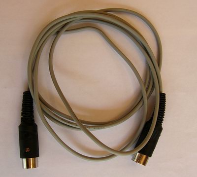
Constructing the cable
A cable is required to connect the EVO to the student radio. There
are a number of web sites that explain how to construct such a cable.
The cable described here has a number of key features:
- The cable is a simple two wire 'non-powered' system.
- The cable is 'buffered' to avoid any electrical problems.
- The student radio must be powered up using its own power switch -
remember that the RF must be disabled by removing the student radio
crystal, or removing the RF module.
Note: A number of cables described elsewhere do not have the transistor buffer
that is included in this cable. While these cables will work there is a good chance
that they will not work when the EVO's battery is fully charged.
The circuit diagram for the cable is:
The easiest way to make the cable is to build the electronics into
the EVO connector. This is described in the following procedure.
Locate the following components:
- A 7-pin 270° DIN Male plug;
- An NPN transistor (2N2222, PN100, BC547, etc);
- A 4k7 resistor;
- Various lengths of heat shrink tube;
- About 2m length of two wire cable, something thin and flexible
like shielded audio cable is good;
- For a Futaba/Hitec student a 6-pin 270° DIN Male plug;
- For a JR student a 3.5mm mono audio plug.
|
 |
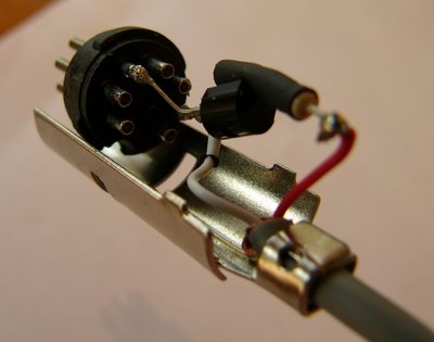
To construct the EVO end of the cable proceed as follows:
- Take the 7-pin 270° DIN Male plug to pieces. You will have
the plastic outer cover, two metal bits and a black bit which has the
pins embedded in it.
- Solder the transistor's base to the resistor and cover this with
some heatshrink.
- Place some heatshrink over the transistor's collector and
bend the collector and emitter legs so that they will connect to the appropriate places
on the DIN plug pins.
- Solder the emitter and collector legs to the pins on the connector.
- Strip the cable and cut the various conductors to the correct length.
The 'ground' conductor needs to connect to the transistor's emitter and
the 'signal' conductor connects to the resistor.
- Solder the wires to the correct places.
- Double check all connections and make sure there are no short circuits.
- Put the metal covers onto the plug and crimp the wire into the metal
cover as a strain relief.
- Slide the plastic outer cover onto the cable and push it all the way
to hold the DIN plug together.
|
 |
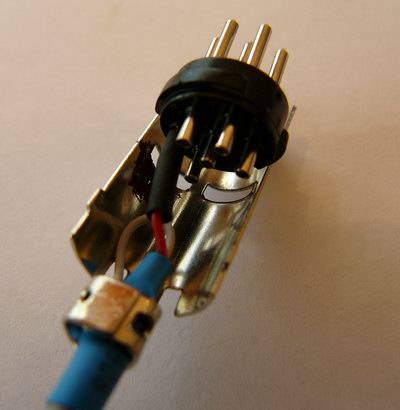
For a Futaba connection proceed as follows:
- Take the 6-pin 270° DIN Male plug to pieces. You will have
the plastic outer cover, two metal bits and a black bit which has the
pins embedded in it.
- Slide the plastic outer cover onto the cable.
- Strip the cable and cut the various conductors to the correct length.
Note that the 'ground' conductor needs to connect to the metal outer piece of the
DIN connector.
- Solder the 'signal' conductor to the pin on the DIN plug.
- Solder the 'ground' conductor to the area just inside the crimp area
of the metal outer. (This is the piece of the outer that has the
funny 'hump' in the middle that matches up with the key in the connector.)
- Double check all connections.
- Crimp the wire into the strain relief.
- Slide the plastic outer cover onto the plug.
|
 |
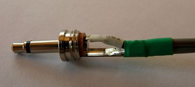
For a JR connection proceed as follows:
- Take the audio plug to pieces. You will have
the plastic outer cover and the plug.
- Slide the plastic outer cover onto the cable.
- Strip the cable and cut the various conductors to the correct length.
Note that the 'ground' conductor needs to connect to the metal outer piece of the
connector and the 'signal' conductor goes to the tip of the connector.
- Solder the wires to the connections.
- Double check all connections.
- Crimp the wire into the strain relief.
- Slide the plastic outer cover onto the plug.
|
 |
Connecting to the student radio
- Plug the student end of the cable into the student radio.
- Ensure that the student's RF module is off. Either remove the crystal or
remove the RF module for modular transmitters.
- Turn on the student's radio.
Configuring the student radio (Part 1)
The first step in configuring the system is restoring the student radio to a 'basic'
configuration. The objective is to remove all the mixers and special functions from the
student radio and configure the radio so that each control input (Throttle, Rudder, Aileron
and Elevator) is transmitted unmodified via its own servo channel. The EVO
will be configured to read the information from each servo channel and assign
the information to the control input to the EVO.
The basic procedure is explained below; you may need to modify this
procedure slightly depending on the type of student radio.
- If the student radio has multiple model memories select an unused model memory.
This memory will be the one to select for 'student' use with the EVO.
- Set the travel to 100% for all channels.
- Set the rates to 100% for all channels.
- Clear the exponential for all channels.
- Clear the servo reverse for all channels (ie. set all channels to normal)
- Clear all the trim memory and set sub-trims to zero.
- Turn off all the mixes.
Connecting to the EVO
- Plug the teacher end of the cable into the EVO.
- Turn on the EVO.
Configuring the EVO
This step by step guide to configuring the EVO as a teacher radio goes through the
following steps:
- Record desired control throws;
- Enable a widget to control training mode;
- Assign the student radio's servo channels to the correct control functions.
Important Note:
The EVO has separate training configuration for each model memory.
This procedure explains how to configure the EVO for the first model,
a section at the end of this procedure explains how to configure
other models for training mode.
The most important decision to make is which widget you want to use to
select 'student' mode. My preference is the 'J' widget and I configure
this widget so that in the down position it selects the student radio. This
makes it easy to regain control by flicking the switch up.
Important Note: The following procedures must be carried out
with the aircraft switched off. During these procedures the servos
will move unpredictably. Systems with ESC may find that full throttle is
generated unexpectedly. You have been warned!
The initial configuration of the teacher/student system will be easier if
you select a model on the EVO that has at least the four basic controls
(Aileron, Rudder, Elevator and Throttle). The reason for this is that you
will need to use the EVO's servo monitor screen to check the calibration of
the teacher/student system and this is much easier if the
selected EVO model has a servo channel that is driven by each of the control
inputs.
|
Turn the EVO on with the RF enabled. Select a model that
has the four basic control inputs used. Ensure the throttle
is at 'idle' (ie. the control stick at minimum).
|
|
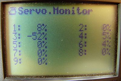
Select the Servo->Monitor function and then use a digi-adjuster to move to the numeric
display. Record the displayed values as the 'neutral' position.
|
 |
|
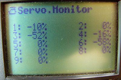
Move the Aileron to the full left position and record the servo positions.
|
 |
|
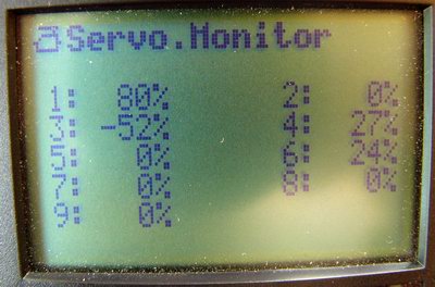
Move the Aileron to the full right position and record the servo positions.
|
 |
|
Repeat this procedure for the Rudder and Elevator at either extreme and also
for the Throttle at maximum.
You will now have a table of servo positions that correspond to neutral and the limits
of each of the controls. You should see that one of the EVO channels will
serve as the primary indicator of the input control position.
For example, in the images shown Channels 1 and 6 are the aileron servos, with channel 6 being
the best indicator of full left aileron and channel 1 being the best indicator of full right aileron.
(This is a dual aileron servo model with differential which explains the different movements.)
|
| Control | Left/Down | Centre | Right/Up |
|---|
| Aileron | Servo 6 = -58% | Servo 1 = 8% | Servo 1 = 80% |
| Rudder | Servo 4 = -34% | Servo 4 = 5% | Servo 4 = 43% |
| Elevator | Servo 2 = 38% | Servo 2 = 0% | Servo 2 = -30% |
| Throttle | Servo 3 = -53% | N/A | Servo 3 = 76% |
|
|
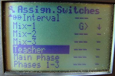
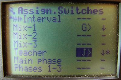
Select Setup->Assignment->Switches then scroll down until
the Teacher switch is visible.
|
 |
|
Ensure the widget that you want to use to select 'student' mode is
in the 'teacher' position. Select the 'Teacher' control by pressing
the 'Enter' button and then press 'Enter' again to acknowledge that
you are changing the template for all models. Then move the widget to
the 'student' position. Press 'Enter' to complete the assignment.
|
 |
|
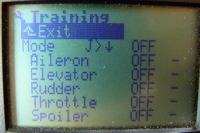
Now move to the Setup->Training menu and return the 'Teacher widget' to
the 'teacher' position.
|
 |
|
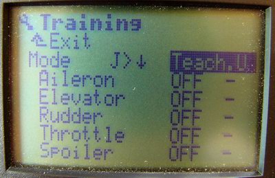
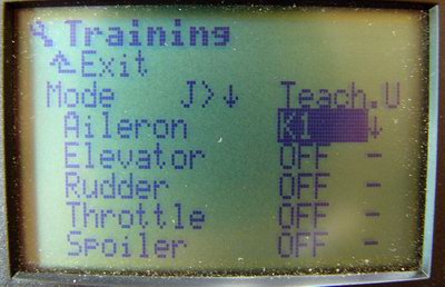
Change the 'Mode' to 'Teach U'. This selects teacher mode
with the student radio set to 'universal' timing (ie. 1.5msec neutral
pulse width).
|
 |
|
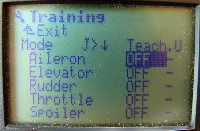
Move to 'Aileron' and select it.
|
 |
|
Move the aileron control on the student radio. The 'OFF' will change
to the letter 'K' (for channel in German) followed by a number. The number
should be the servo channel that the student radio uses for this function.
(For Futaba users this is: Aileron = K1, Elevator = K2, Rudder = K4, and
Throttle = K3). Press 'Enter' to complete.
|
 |
|
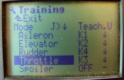
Now repeat this process for each of the other control functions until you
have all of the control functions assigned to the appropriate student
radio channel.
|
 |
|
Return to the Servo->Monitor function and then use a digi-adjuster to move to the numeric
display. Check that moving the EVOs controls governs the servo positions.
Move the 'Teacher widget' to the 'student' position and then move each of the student radio
controls. You should see that the EVOs servo positions are now controlled by the student radio.
At this stage do not worry about the exact amount of control the student radio has,
instead check that the student radio is moving the controls in the correct direction.
For example, move the student aileron left and then look at the servo monitor. If the servo
positions are moving towards the 'left aileron' position (as you recorded earlier) this is OK.
However, if the servos are moving towards the 'right' position you will need to program the
EVO to reverse the signal. Check each of the student controls and note which ones need to
be reversed.
|
|
|
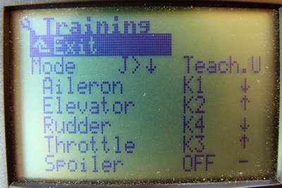
Return to the Setup->Training screen. For each input that needs to be reversed
scroll down to that input, select the input by pressing 'Enter' and then reverse the signal
by pressing 'REV/CLR'. You will notice the arrow after the channel number will change direction.
Press 'Enter' again to complete the change.
Repeat this process to reverse any other input that needs reversing. For a Futaba
student radio you will probably need the Elevator and Throttle inputs reversed.
Note down the settings on this screen, these are the settings that you will
need to copy to other models in the EVO if you want to use them in training mode.
(Note: You will only need to follow the student radio configuration below once.
A correctly configured student radio will work with all models in the EVO without
adjustment.)
|
 |
This completes the configuration of the EVO for the first model.
To use a different model for training you will need to configure the values on the
Setup->Training menu for that model and make the values the same as those
that you noted down in the step above.
Configuring the student radio (Part 2)
Now that the EVO is configured the next step is to configure the student radio so that the
controls on the student radio provide exactly the same amount of control as the controls
on the EVO.
Switch the EVO to 'student' mode and select the Servo->Monitor function and
then use a digi-adjuster to move to the numeric display.
Adjust the sub-trim (or other trim function) on the student radio so that the centre
(neutral) position for each of the controls is generating the correct servo position.
(On a Futaba 6XAS this required a sub-trim of -20 on each channel).
Then adjust the servo travel for each channel on the student
radio so that the EVO servo positions
for full left and right (also full up and down) student controls are the same as they were with the EVOs
controls. (On a Futaba 6XAS this required setting the ATV to +/- 120% on all channels.)
As a final step I would now suggest configuring the student radio dual rate switch
if the radio has one. I would suggest setting the dual rates to about 70% on the student
radio. The purpose of this is that with the student dual rates set to 70% the student only
has about 70% of normal control input movement, while the teacher has the normal 100%.
As the student progresses and does not over control the aircraft the student
radio can be set to normal
rates and will have the same inputs as the EVO.
Using the system
To use the training system proceed as follows:
- Connect the training cable;
- Ensure the RF on the student radio is disabled (ie. remove crystal or RF Module);
- Set all student controls to neutral, ensure throttle is at idle;
- If the student radio is configured for dual rates select either low rate or normal rates
accoding to the student's needs;
- Turn on the student radio;
- Verify that the student radio has the correct model memory selected;
- Ensure that the EVO's 'Teacher' widget is in the 'teacher' position;
- Turn on the EVO;
- Check the correct model is selected;
- Check the Setup->Training menu to ensure that the mode is set correctly
('Teach U') and that the channel assignments are all present;
- Turn on the aircraft receiver;
- If the aircraft is an electric model with a programmable ESC perform the correct sequence
to set the throttle range;
- Verify control surface operation from the EVO;
- Switch to 'student' mode and verify that there is no movement of
any control surfaces when the switch-over occurs;
- Verify that the student has control of all surfaces;
- Switch back to 'teacher' mode;
- Proceed with instruction!
Useful tips
EVO powerup
If the current model has training mode enabled when the EVO is turned on
the EVO will automatically switch to the Setup->Training menu.
This can be annoying, however, it does inform you that training mode
is enabled.
To stop this from happening the Mode setting should be
altered to 'Off'. This will not alter the saved channel assignments for
the control functions. When it is again desired to use training mode
just alter the Mode back to Teach U.
No student radio connected
If there is no student radio connected,
or the student radio is powered off,
the EVO will 'ignore' the setting of the 'Trainer' switch
and revert to the EVOs controls.
This is a useful safety measure. However, if the student powers off
their radio, or the cable becomes unplugged, the teacher needs to
be aware that they will regain control of the aircraft even when the
switch is in the 'student' position.
Partial control
In some situations it may be desirable to remove some functions from
control by the student. For example, you may wish to remove the throttle
from student control and control it yourself at all times.
Important Note: The following procedures must be carried out
with the aircraft switched off. During these procedures the servos
will move unpredictably. Systems with ESC may find that full throttle is
generated unexpectedly. You have been warned!
This is easy to accomplish, use the Setup->Training menu on
the EVO and select the control input that you want to remove from student
control and then adjust the channel number to 'OFF'. All input controls
that are selected as 'OFF' are always under control of the EVO.
To return the control to the student just restore the correct channel
number and control direction.
Remember to check the 'Mode'
It is very easy to set the 'Mode' to 'Teach M' by mistake. If this occurs
the system appears to be working correctly, however, the student's radio is
significantly out of trim.
It is important to check that when all controls are in neutral that
switching from 'teacher' to 'student' causes no control surface movement.
Cross mode training
The EVO and student's radio do not need to be configured with the same mode.
The training system will work correctly if the EVO is in say 'Mode 2' and the
student is configured for 'Mode 1'.
This permits training of students who are using a different mode to the
instructor.
Remember the other EVO controls still work
Even when switched to student mode the non-student controls still function on
the EVO. In particular it is worth remembering:
- The throttle kill function is available;
- The various other switchs also function (eg. dual rates, aileron->rudder, etc.).
Limitations
There are a few functions that do not work quite as you may expect in
'student' mode. The main culprit here is that EVO switches that are assigned
to control inputs continue to function from the EVO even when in 'student' mode.
For example, if a timer switch is configured to trigger from the throttle
input position it will always be controlled by the EVO's throttle.