Lost Model Alarm
13 February 2004
This project documents how to build and construct your own
Lost Model Alarm (LMA) using a Microchip
12F675 PIC and a small number of standard components.
Important Note
This information is provided on a
'as-is' basis. Model aircraft are not toys. Construction, and
use, of this device is at the users own risk.
Most simple PIC programmers do not
verify that the device has been programmed correctly by using
high and low supply voltages to the PIC. This type of programmer
is not normally considered a production environment programmer
and there is a risk that the PIC has not been correctly programmed
even when the software says it has been.
Background
There are a number of commercially available LMAs and also
a number of other projects for DIY LMAs.
The various commercial units, and DIY designs, offer a wide
range of features and facilities. The features considered desirable
differ widely from unit to unit. This design provides a number
of features that I considered useful.
This project grew out of the desire to add a basic LMA to
the Brushed Motor ESC project, to investigate LMAs this project
was created as a separate standalone project.
In its simplest form this LMA operates without any signal from the
receiver, the LMA will give a short beep at powerup and then
the LMA will sound its alarm sequence
after a fixed period from power on or if
the battery voltage is too low. The alarm consists of a number of
beeps that sound once every 30 seconds.
The more sophisticated versions of this LMA monitor one of the
receiver channels and will sound the alarm on loss of signal. In
addition the LMA can be configured to sound the alarm under explicit
control from the transmitter.
A further facility of this LMA is the ability to count receiver
glitches and to report on the number of glitches recorded.
In short, this LMA offers a range of facilities that the user
can configure when constructing the LMA. The LMA can also be used for
other tasks such as a low throttle glow plug driver.
What this LMA offers
This LMA design offers the following features, all features
are configurable when the LMA chip is programmed:
- Time based LMA activation, the LMA can be configured to turn
the alarm on after between 1 and 255 minutes after power is applied.
- Activation of the alarm after loss of received servo pulses.
- Activation of the alarm when the received servo pulse is
less than, or greater than, a specific value. The activation
point is configured in the LMA at any time.
- Monitoring of receiver glitches, these are servo pulses that
are outside tolerances or too far apart.
- Monitoring of battery voltage with a special alert sequence
for the low battery condition.
- The ability to drive a variety of output devices including:
either AC piezo transducers, DC buzzers, LEDs or other devices.
The LMA has two output pins which can either be configured to
drive a single 50mA load, or two loads up to 25mA each. Note: that
the LMAC configuration has only one 25mA output signal.
- Configurable alarm sound, duration, silent period etc.
In most cases these options are separately configurable in the LMA
and will operate together. For example it is possible to construct
an LMA with Time Based Activate only, or Time Based Activation and
Glitch Monitoring only, or any combination of the options mentioned
above.
Time based activation
In its simplest mode of operation the LMA just waits for a
period of time to expire and then turns on the alarm. Once the
alarm is turned on due to the expiry of the time it will stay
on until the battery is flat.
Activation on Loss of Servo Pulses
By monitoring a receiver channel the LMA can detect loss of
valid signals. A valid signal is considered to be any received
servo pulse in the range of 0.768ms to 2.559ms that occurs at
least once every 25ms.
If valid pulses stop for a period exceeding 100mS the LMA
alarm will activate. The alarm will be canceled if 10 valid
receiver pulses in a row are detected.
Activation under command
The LMA can be configured to monitor a receiver channel and
to activate the alarm if the servo position on the channel is above,
or below,
a particular setting. In order to activate the alarm the servo
must be in the position for at least 250ms.
This facility is useful for users with a spare channel, or
a channel that is not normally set beyond a particular point.
The purpose is that when a model is lost, but still probably
within range, the LMA can be triggered without either waiting
for the time based activation or loss of signal activation.
This stops servos etc. from flapping around when there is
no receiver signal and possibly damaging the aircraft more, or
using valuable battery power.
The command activation point may be either preset in the software
or configured into the LMA during operation and is easy to alter
at any time.
Glitch counter
The glitch counter system permits the LMA to monitor a receiver
channel and count the number of glitches, any received servo
pulse outside the range of 0.768ms to 2.559ms, or servo pulses
more than 25ms apart.
The LMA can be commanded to 'beep out' the count of glitches
using a small switch or jumper pins on the LMA.
Battery Voltage Monitor
The battery voltage monitor enables the LMA to monitor the
supply voltage to the LMA. If the supply voltage drops below a
voltage that is set during construction the LMA will commence sounding
a special low voltage alarm sequence.
The LMA will exit the low voltage alarm sequence when the voltage
is restored to a level above the detection point.
Output Devices
The LMA can control a variety of output devices, including
directly driving AC Piezo transducers. The AC transducers offer
the lowest cost alarm and have acceptable volume levels. (It is
also possible to use two transducers to get increased volume
levels.) The
AC Piezo transducers have a specific resonant frequency and you
must configure the LMA software with the resonant frequency of
your transducer. To control AC transducers the LMA output signals
are driven in a square wave and the appropriate frequency.
Alternatively the LMA can control DC buzzers, or Piezo units
with inbuilt drivers, or may other devices. In this case the
LMA output signals are driven to +volts when the alarm is to
sound.
The LMA has two output signals that are each capable or sourcing
25mA. These outputs can be used independently to drive two output
devices less than 25mA each, for example a buzzer and a LED,
or joined together to drive a single device requiring up to 50mA.
Configurable
The LMA has many configurable parameters in the source code
that users can adjust to get their desired mode of operation.
Software Development Environment
This software was developed with the MPLAB
IDE from MicroChip. To build this LMA it is very likely that
you will need to use this software to produce the .HEX file for
programming your LMA. There are too many different configuration
parameters to publish on the Internet all the possible LMA .HEX
files.
After you have installed the MPLAB IDE proceed as follows:
- Create a directory somewhere on your Windows system. the
MPLAB IDE does not like path names that are too long (greater
than 30 characters or so) - so stick to a simple short name.
For example: C:\PIC\LMA
- Copy the lma.asm file from the links below into your directory.
- Start the MPLAB IDE.
- Select Project->Project Wizard.
- Click Next.
- Select 'PIC12F675' as the device, click 'Next'.
- Select 'Microchip MPASM Toolsuite' as the Active Toolsuite,
click 'Next'.
- Enter a name for your project and then use the 'Browse' facility
to set the Project Directory to the directory you created at
the first step, click 'Next'.
- Add the lma.asm file that you copied into the project directory
to the project by double clicking the file name in the left hand
pane, the file will appear in the right hand pane. Do NOT
check the box next to the file. Click 'Next'.
- Click 'Finish'.
- The workspace will open and you will see a project window
that shows one Source File.
- You should now be able to assemble the PIC code by pressing
F10 - this will produce a file called 'lma.hex'.
- To alter the parameters double click on 'lma.asm' in the
project window and the assembler source will now appear in a
new window, make the changes you require in this window.
- After you have made you changes press F10 to assemble the
code.
The MPLAB IDE has full support for simulation that permits
you to fully check the operation of the LMA. However, the use
of these facilities is beyond the scope of this document. Users
who just want to build a 'custom' version by modifying standard
parameters of the LMA should have no problem using the IDE
to assemble and test their code.
The software options
The following step-by-step procedure will permit you to configure
the LMA software for your application. There are 4 basic configuration
values that need to be set, these values are at the top of the
LMA source file and will look something like this in the standard
file:
  POWERUPBEEP	equ	1	; 0 or 1
  LMARUNTIME	equ	0	; time in minutes that the LMA should turn on
  LMAONLOS	equ	1	; turn on LMA on loss of receiver signal
  LMAONCMD	equ	1	; 0,1 or turn on at < usec
  GLITCH_COUNT	equ	1	; 0 or 1
  LMAFREQUENCY	equ	4500	; 1 or frequency in Hz
This procedure will permit you to determine the value to assign
to each parameter, you then use the MPLABS IDE to alter the source
code and then press F10 to build the LMA.HEX file for programming
the 12F675.
- Determine if you have an AC siren, or a DC buzzer. The retailer
should know which is which, I would suggest an AC piezo as the
lowest cost and simplest to use. If you have an AC siren go to
step 3.
- You have a DC buzzer, set LMAFREQUENCY to 1.
Go to step 4.
- You have an AC siren, you need to know the resonant frequency
in Hz. (If you have the frequency in kHz, for example 4.2kHz,
then multiply the number by 1000 and you have Hz). Set LMAFREQUENCY
to the frequency in Hz.
- Determine if you want the LMA to turn on at nominated time
after power up. If you do go to step 6.
- You do not want the LMA to turn on at a nominated time, set
LMARUNTIME to 0. Go to step 7.
- You want the LMA to turn on after a specific time. You need
to determine the time in minutes and it must be between 1 and
255. Set LMARUNTIME to the time in minutes.
- Determine if you require the glitch monitor facility.
If you want this facility go to step 9.
- You do not require the glitch monitor facility so set
GLITCH_COUNT to 0. Go to step 10.
- You require the glitch monitor facility so set
GLITCH_COUNT to 1.
- Determine if you want the LMA to monitor the
receiver pulses and activate the alarm on loss of signal.
If you want this facility go to step 12.
- You do not require the alarm to activate on LOS, set
LMAONLOS to 0. Go to step 13.
- You do require the LMA alarm to activate on LOS, set
LMAONLOS to 1.
- Do you require the LMA to activate on command? If you do
not then set LMAONCMD to 0. Otherwise
set LMAONCMD to 1 if you want configurable
command point. For a fixed command on point
when the receiver pulse is on at < X.YYYmsec set
LMAONCMD to -XYYY,
to command on at > X.YYYmsec set LMAONCMD to XYYY.
- Determine if you want the LMA to produce a very short beep
when powered on
to indicate that it is functioning. If you want the this facility
go to step 16.
- You do not require the power up beep, set POWERUPBEEP
to 0. Go to step 17.
- You do require the power up beep, set POWERUPBEEP to
1.
- Determine if you require low voltage detection in the LMA,
if you do goto step 19.
- You do not require low voltage detection, set LOWVOLTS
to 0. Go to step 20.
- You require the low voltage detection facility. Set LOWVOLTS
to the desired low voltage indication point in mV. For example, 4.2V would
be 4200. In addition you need to know the reference voltage you are
using. If you construct the LMA as shown in the diagrams the reference
voltage will be 3.3V (or 3300mV) and you do not need to alter the
software configuration. If you have a different reference voltage you
should set LOWVOLTSREF to the reference voltage in mV.
- Software configuration is now complete.
Circuits
There are two possible basic circuits that will apply to your
LMA. The simplest one is when there is no receiver channel to
monitor (LMAA), the more complex (LMAB) is when there is a receiver
channel to monitor. It does not matter if you use the more complex
LMAB circuit with an LMA that only requires LMAA.
There are also a number of possible alarm device connections
and these are shown on a separate diagram. You will need to select
from the possible alarm device configurations that suit your
requirements.
You can determine the circuit that your LMA requires by loading
the LMA.HEX file into your PIC programmer and looking at the
text display of the PIC contents you will see the file name,
version number, and circuit type displayed in the text area.
Where is everything?
The files available for download are:
| File Name |
Description |
| lma.asm |
Ver 1.2: PIC 12F675 Assembler Source |
| lmaa.gif |
Rev B: Circuit diagram for basic LMA - LMAA |
| lmab.gif |
Rev B: Circuit diagram for complex LMA - LMAB |
| lmac.gif |
Rev A: Circuit diagram for complex LMA - LMAC |
| lmaalrm.gif |
Rev B: Circuit diagram showing various LMA alarm options |
How to build one
So after all that you would like to try constructing one of
these, what do you do?
Because of the large number of options possible for the LMA
this section is a guide only. The pictures shown in this section
are for the construction of an LMAB design with a single AC piezo
siren using the soldered leg construction system.
This LMA when fully assembled weighs 10gms (+/- 2gms).
| Step |
|
Description |
| 1 |
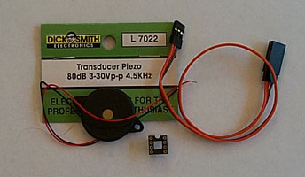 |
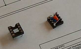
Purchase your components.
I would suggest a machined pin 8-pin socket to hold the PIC.
These sockets last longer and also have more robust legs for this
construction technique.
The servo cable can be purchased with only one connector and
bare wires on the other end. Alternatively, you may want to consider
purchasing a 300mm servo extension lead and cutting it in the
middle you can then join the wires together and form an extension
cable with the LMA in the middle, or constructed as a Y-cable
with the LMA at one end.
You also need to select a piezo, buzzer or LED for the alarm
output. If using an AC piezo transducer you can build a louder
unit by using two transducers, one on each output.
|
| 2 |
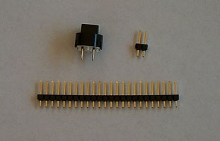 |
If you are constructing the LMAB circuit you will need either
a small push button switch, or a 2 pin header. This switch is
required for programming the LMA command point, and also for
obtaining the glitch count. A 2 pin header block is quite suitable,
you can use a normal PC jumper to close the contacts during command
programming, and to obtain the glitch count just short the pins
together with a coin or something. If you prefer a small switch
is also a possibility.
This example uses a 2 pin header block. These are normally
sold in longer strips and you just break off two pins.
|
| 3 |
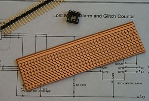 |
Decide if you need a small piece of veroboard to assemble
your LMA on. In many situations you may just be able to assemble
the components together just by soldering to the legs
of the 8-pin socket. This is
particularly suitable of the entire LMA and piezo is going to
be glued together and then covered with a piece of heat-shrink
tubing.
Alternatively for a more complex LMA with multiple output
devices you may want to use a small piece of veroboard to hold
the components. This technique is more suited when you want to
construct an LMA that will be permanently installed and you don't
need to cover the LMA - just build it into the plane.
This example uses the soldered leg construction technique.
|
| 4 |
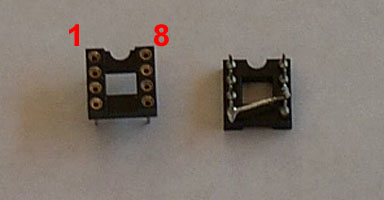
| Take the 8-pin socket and solder the fixed wires
between pin 3 and 5. Note that the socket has a notch to indicate
which end of the socket is pin 1 and 8. |
| 5 |
 |
Then attach the two capacitors C1 and C2 across
pins 1 and 8 of the socket. Check the polarity of C2 carefully
to ensure that the +ve goes to pin 1 of the socket. |
| 6 |

| Tin the end of the servo lead, or leads if
you are making a Y-cable at the same time, that serves as the
power and servo signal input to the LMA. If you are constructing
the LMAA circuit you should cut off the servo signal and insulate
it with a small piece of heat shrink tubing. For the LMAB circuit
attach R2 to the servo signal and cover with heat shrink tubing. |
| 7 |
 |
Now attach the servo cable to the power supply
pins and also R2 to the servo input signal (pin 6)
if you are constructing
LMAB. Take care to connect the power to the 8-pin socket the
correct way round. The positive volts must go to pin 1. |
| 8 |
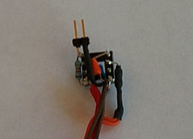 |
If you are constructing LMAB you now need to
connect the switch and its associated resistor to the PIC. Do
this in such a way that the switch, or header pins, are going
to be accessible once construction is complete.
This is best done soldering R1 between pins 1 and 4, and
then the switch, or header pins, between pins 4 and 8.
You may need to use a short length of insulated wire to
help join these components up.
|
| 9 |
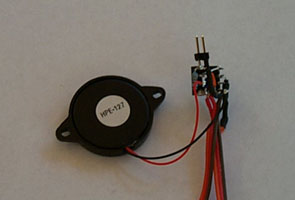 |
Connect the buzzer, siren or LEDs that you are
going to use with the LMA. Again if you are installing a high
intensity LED ensure that it is oriented so the lens will be
visible once construction is complete. |
| 10 |
|
Now is the time to test your LMA and ensure correct
operation of the LMA. See below for the
test procedure. |
| 11 |
 |
If you are going to join the piezo and LMA into
a single unit use a small amount of hot glue, RTV silicon, or
similar product to attach the 8-pin socket to the back of the
Piezo. Note: ensure that the piezo's vent hole is on the
outside and also that the IC socket is mounted so that the chip
can be changed. |
| 12 |
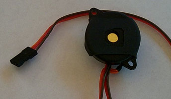 |
You can now shrink a piece of heat shrink onto
the LMA. After shrinking the tube cut the tubing away to expose
the piezo vent hole - otherwise you won't get much sound. |
| 13 |
|
Follow the user instructions below. |
Test Procedure - LMAA circuit
Note: during testing the
alarm may sound and could be very loud.
You may want to muffle the siren or buzzer while working on the
unit to reduce the volume.
TIP: If you want to reduce the noise of the piezo or buzzer when testing,
just put a piece of thick tape over the orifice - this cuts the noise way down
and saves your ears.
- Ensure that there is no PIC installed in the IC socket.
- Plug the servo cable into a receiver channel and connect
the receiver to a battery pack.
- With a multi-meter check the voltage between pins 1 and 8
- pin 1 should be 4.8V (5V if you are using a BEC).
- If you have configured the LMA for low voltage detection check
the voltage between pin 6 (T1) and pin 8.
Pin 6 should show 3.3V, if it does not
then check the wiring and also the polarity of D1.
- Remove the battery pack.
- Check the software options using the
information in the section above. Generate the LMA.HEX file.
- Load the LMA.HEX file into your programming software and
check the text display of the PIC contents to ensure that it
specifies the circuit type you expect.
- Program a PIC with this code.
- Insert the programmed PIC into the socket.
- If you are constructing an LMAA circuit your LMA will only
activate based on run time. Apply battery power to the receiver.
There should be no alarm active at this
point. Check the voltage between the alarm driver pins
and ground - there should be 0 volts.
- Now you need to wait for the number of minutes that you configured
into the LMA. After this time the alarm should start sounding.
If the alarm does not sound check the voltage between ground
and the alarm driver pins. When the alarm is active you should
measure either a DC or AC voltage of 4.8V on the alarm driver
pins.
- To check the low voltage detection you can connect the LMA to
a known low voltage battery pack. Alternativly you can use a 3.6V
supply such as a 3 cell pack. The low voltage alarm should sound.
- The test is complete.
Test Procedure - LMAB & LMAC circuit
Note: during testing the
alarm may sound and could be very loud.
You may want to muffle the siren or buzzer while working on the
unit to reduce the volume.
TIP: If you want to reduce the noise of the piezo or buzzer when testing,
just put a piece of thick tape over the orifice - this cuts the noise way down
and saves your ears.
- Ensure that there is no PIC installed in the IC socket.
- Plug the servo cable into a receiver channel and connect
the receiver to a battery pack.
- With a multi-meter check the voltage between pins 1 and 8
- pin 1 should be 4.8V (5V if you are using a BEC).
- With a multi-meter check the voltage on pin 4 of the socket.
This should be 4.8V when the switch is not pressed and 0V when
the switch is pressed. If this is not correct check your wiring.
- If you have constructed the LMAC curcuit
for low voltage detection check
the voltage between pin 7 (T4) and pin 8.
Pin 7 should show 3.3V, if it does not
then check the wiring and also the polarity of D1.
- Remove the battery pack.
- Check the software options using the
information in the section above. Generate the LMA.HEX file.
- Load the LMA.HEX file into your programming software and
check the text display of the PIC contents to ensure that it
specifies the circuit type you expect.
- Program a PIC with this code.
- Insert the programmed PIC into the socket.
- Turn on your transmitter. If you have configured activation
under command you should set your transmitter to a setting that
indicates you do not want the alarm on.
- Apply the battery power.
- If you have not configured the LMA for programmable activation
point you should skip to step 23.
- If you have configured the LMA for a programmable activation point the
beeper should start sounding the 'not programmed' code of one
short followed by one long beep that is repeated forever. If
this does not occur you should check the alarm driver connections.
- Remove the battery power.
- Hold down the switch, or place the jumper on, and reapply
power.
- The LMA should produce one short beep to indicate that programming
mode has been entered.
- Move the transmitter control to the extreme position that
should cause the LMA to activate.
- Release the switch, or remove the jumper.
- The LMA will produce one short beep, followed a short time
later by two short beeps that indicate the position has been
read. If the LMA produces the 'not programmed' code (one short
followed by one long beep) then you have a problem in the receiver
pulse wiring (or the transmitted is turned off).
- Move the transmitter control away from the activation position
to the normal limit position (where you do not want the LMA activated).
The LMA turn on point will be set midway between this position
and the previous position.
- Press and release the switch, or connect and remove the jumper.
The LMA will produce the 'programming complete' code.
- When you do not have a programmable activation point, or
have just completed programming mode, the LMA should be silent.
If you hear the LMA alarm (a series of rapid beeps every 30 seconds)
you have a problem with the receiver pulse wiring (or your transmitter
is turned off).
- If the LMA is configured for activation by command move the
transmitter control to that position - the LMA alarm sequence
should comments. Move the transmitter control to the normal position
and the alarm should stop.
- If the LMA is configured for activation on loss of servo
pulse turn the transmitter off - the LMA alarm sequence should
commence. Turn the transmitter back on and the alarm should stop.
- If you have the glitch counter configured into the LMA try
pressing and releasing the button, or temporarily shorting the
jumper pins. The LMA should indicate the number of glitches so
far by sounding the beeper to indicate a number between 0 and
99.
- To check the low voltage detection for LMAC
you can connect the LMA to
a known low voltage battery pack. Alternativly you can use a 3.6V
supply such as a 3 cell pack. The low voltage alarm should sound.
- Your LMA should now be fully functional. Testing is complete.
User Instructions
Programming the activation point
- Remove power from the LMA.
- Turn on the transmitter.
- Hold down the switch, or place the jumper on, and reapply
power.
- The LMA should produce one short beep to indicate that programming
mode has been entered.
- Move the transmitter control to the extreme position that
should cause the LMA to activate.
- Release the switch, or remove the jumper.
- The LMA will produce one short beep, followed a short time
later by two short beeps that indicate the position has been
read. If the LMA produces the 'not programmed' code (one short
followed by one long beep) this indicates that a stable received
pulse was not available - either the transmitter is turned off or
there is no receiver pulse for some other reason.
- Move the transmitter control away from the activation position
to the normal limit position (where you do not want the LMA activated).
The LMA turn on point will be set midway between this position
and the previous position.
- Press and release the switch, or connect and remove the jumper.
The LMA will produce the 'programming complete' code.
Obtaining the glitch count
- Press the button, or short the header with a coin.
- The LMA will beep the number of glitches it has registered.
- If there have been no glitches a single long beep will sound.
- If there have been more than 99 glitches two long beeps will sound.
- For between 1 and 9 glitches than number of short beeps will
sound. For example, 4 glitches will sound four short beeps.
- For between 10 and 99 glitches the LMA will beep out the tens and
then the units with a pause between them.
A unit of zero is indicated by a long beep. For example, 13 glitches
would be 1 short beep, a pause, and then 3 short beeps.
LMA codes
| Sound |
Meaning |
| 1 very short beep |
LMA Startup Sequence
Indicates that the LMA is operating. This code should occur
immediately after power up, or when programming is complete.
|
| 2 very short beeps once every 30 seconds |
LMA Alarm Sequence
The LMA alarm condition is active.
|
| 1 very short beep once every 5 seconds |
Low Battery Sequence
The LMA has detected a low battery condition.
|
| Short beep, long beep repeated |
Not Programmed
The LMA is configured for programmable activation point and
this point has not yet been configured. Power the LMA off and
follow the instructions for programming the activation point.
|
| Long beep repeated |
Programming Failure
The LMA is in programming mode however programming cannot
be completed. Power the LMA off, check that the transmitter is
turned on and attempt the programming again.
There is a possiblility that this will occur if the programmable
storage in the PIC is faulty, however, normally it indicates
that the receiver servo pulses are not present.
|
| Single short beep |
Entering programming mode
The switch was pressed at power up and the LMA has entered progamming
mode. Various sequences of short beeps will guide you through
programming mode.
|
| Three short beeps |
Exit programming mode
The LMA has completed programming and is enntering normal operating
mode.
|
| Other Sequence |
Glitch monitor output
The glitch monitor indicates the number of received glitches
|
Frequently asked questions
Q: I want to control the LMA using the gear switch how
do I configure this?
A: Set the gear switch to the position that you want the LMA
activated in. Hold down the switch and apply power. When you
hear the single beep release the switch. When you hear the the
two short beeps move the gear switch to the normal position and
then press and release the button. The LMA will sound the programming
complete code. The LMA will now activate when the gear switch
is moved to the activation position.
Q: How do I get a louder sound?
A: You can increase the volume in a number of ways:
- Use two piezo transducers, one on each output.
- You can use a different buzzer or siren with a higher output.
Just remember that the PIC can only drive 25mA per output pin. A
higher current that this would require a transistor or FET buffer.
- You can power the buzzer from a separate battery using a
transistor or FET buffer.
- You may be able to modify a 'personal alarm' keyring or similar
device to be controlled by the LMA.
Various of these options are shown on the circuit diagrams.
Q: Can I use this LMA for anything else?
A: Yes, the LMA can be used as a switch for various purposes.
It is really only a programmable switch with a number of configurable
parameters.
For example, to use the LMA PIC as a glow switch that turns
the glow plug on at low throttle proceed as follows: set
LMARUNTIME to 0, LMAONLOS to 0,
LMAONCMD
to 1, LMAFREQUENCY to 1 and
GLITCH_COUNT to 0. Build the LMAB circuit
with a LED on one output pin, and a FET or transistor driver
controlling the glow power supply on the other alarm output.
To set the turn on point proceed as follows: set the transmitter
throttle to the point that turn on is required, hold down the LMA
switch, power the LMA and receiver on, wait for programming mode to
commence as indicated by the LED, release the switch, wait for the
continue code to be indicated on the LED, move the
throttle one click higher (where the glow pulg should not be driven),
press and release the switch, programming will now complete.
The glow drive is indicated on the LED for diagnostic purposes.
The glow drive will be turned on whenever the throttle is below the
throttle position set during configuration.