Servo Camera Switch
29 March 2004
This document describes the complete design for a camera switch
that uses a servo to activate the shutter. This page include links
to the complete circuit diagram, the .HEX file required to
program the 12F675, and complete construction details.
The switch consists
of a PIC and a small number of standard components. The Servo
Camera Switch connects inline between the receiver and the
servo and manages the operation of the servo.
Important Note: there is a related design for
direct shutter control for the Aiptek/Jazz cameras.
This document is the base document for direct shutter control design,
with the variations between the two designs explained
elsewhere.
Background
There are a number of options for trigger a camera for AP work:
- The camera can be triggered using an electronic switch circuit
connected between the camera's internal circuits and the receiver.
- The camera can be triggered using a servo connected to the radio
control receiver.
Some form of arm or other mechanism pushes the shutter button.
- The camera can be set to 'auto' shoot, just taking a photo every
preset number of seconds.
For users of electronic switch circuits there are a number of designs
available that each incorporate various features
to manage various cameras. One
of the key features in some switches is the ability to take a photo
every now and again automatically so as to keep the camera from turning
itself off.
This servo camera switch is aimed at providing features similar to some of the
electronic switches for situations where a servo is used to trigger the
shutter.
What this Servo Switch offers
This servo switch offers the following features:
- Threshold switching.
- Automatically takes a photograph to keep camera powered on.
- Automatic picture taking stops on loss of signal.
- Automatic picture taking stops on command.
- Operates in both still photo mode and video mode.
- Operates with cameras that require 'focus' time.
- User configurable parameters.
Threshold switch
Rather than the output servo tracking the input servo command position
the servo switch positions the output servo in the idle position
until the input servo command reaches the trigger position and then the
servo switch commences to take a picture. After taking a picture
the servo switch will wait for the input servo command to return
to the 'no shutter' position before taking another picture.
The picture taking sequence involves moving the output servo
to the focus position for the focus time, then the shutter position
for the shutter time and finally back to the idle position for the
post shutter time.
Automatically takes a photograph
The servo switch monitors the picture taking activity and
will automatically take a photograph after a period of inactivity
to ensure that the camera stays powered on.
Automatic picture taking stops on loss of signal
When the servo switch detects loss of input servo commands the
switch stops automatically taking photos and this permits the camera to
power off. The servo switch continues to produce output servo pulses
to hold the servo in the 'idle' position.
The switch will start automatically taking pictures again
if a manual picture request occurs after LOS.
Automatic picture taking stops on command
With some cameras it is desirable to permit the camera to
automatically power off prior to landing. When the camera powers
off the camera retracts its lens and close the lens cover.
The switch permits the automatic picture taking to be stopped
by holding the input servo command in a particular position
for a set time. Automatic 'keep-alive' will reactivate if
a manual picture request is received.
For example, if the camera automatically powers off after
60 seconds without a picture being taken then 1 minute before you
plan to land this facility is used to stop the automatic picture
taking facility. Then the camera will power off automatically and
retract the lens.
For users who are controlling the camera with a gear channel
the power off position can be the same as the camera shutter
position. In this situation a short press of the shutter
will take a picture, a long press will take a picture and then
command the switch to turn off the keep-alive function. The camera
will then power down after its normal timeout.
Note:
When shooting in video mode with the power off position
the same as the shutter position you should command the power off
at the end of a video sequence, otherwise the power off will
start a new video segment and the camera won't power off until its
memory is full.
Still photo and Video mode
The servo switch will operate in either still photo or video mode.
In video mode the servo switch monitors the 'capturing' status and
correctly operates the keep-alive function only when the camera
is not in capture mode.
Cameras that require focusing time
The servo switch can be configured to move the output servo
to a 'focus' position for some time prior to the servo moving to
the 'shutter' position. This permits the switch to be used with
cameras that require a period of time for focusing prior to
the picture being taken.
User configurable parameters
The servo switch contains a number of parameters that are programmed
by the user, in a similar manner to modern ESCs. The parameters that
are programmed include:
- Servo position for 'idle'.
- Servo position for 'focus'.
- Servo position to 'shutter'.
- Length of time to position servo in 'focus' position.
- Length of time to position servo in 'shutter' position.
- Post shutter delay.
- 'Keep-alive' timeout.
- Input stick position for no shutter trigger.
- Input stick position for shutter trigger.
- Input stick position to disable the keep-alive timeout.
- Length of time the input position must be in disable position
to disable keep-alive.
The switch comes with an initial set of parameters configured into the
switch. These initial parameters are documented in the programming information
below and permit the switch to perform basic functions without significant
programming.
Operational Overview
On power up the servo switch recalls the saved configuration
information.
If there is an error detected in this saved information and programming
mode is not selected the switch will halt and flash the details
of which information is not correctly programmed.
The switch computes the threshold input position, this is half
way between the input position for no shutter and the input position for
shutter trigger.
The switch computes the threshold disable position, this is half
way between the input position for no shutter and the input position for
disable keep-alive.
Next the switch checks to see if the programming mode jumper is installed.
If the jumper is installed the switch enters
programming mode.
The switch commences operation outputing the 'idle' servo pulse
on the servo output signal and monitoring the input servo signal. When
the input servo signal moves from the no shutter trigger to the shutter
trigger side of the threshold input position for a number of
consecutive input pulses the switch commences to activate the shutter.
The shutter activation sequence consists of moving the output servo
to the focus position for the focus time, then moving the output servo
to the shutter position for the 'shutter' time and finally back to the
'idle' position for the post trigger delay time.
The switch then waits for the input servo signal to return again to the
no shutter side of the threshold input position.
When the 'keep-alive' time is reached without any picture being taken
the switch automatically takes a picture using the normal picture taking
sequence.
If video mode is selected the switch considers each of the
shutter activations to be a start or stop video command. The switch tracks
the recording state of the video and only issues 'keep-alive' triggers while
the camera is not recording. In addition, two 'keep-alive' triggers are
used, so that a short video segment is recorded as the 'keep-alive'.
When the switch detects loss of signal on the input servo signal
(a period of 20 receiver frames with no valid input - about 500ms)
the switch will stop automatically triggering the camera. If a manual
picture taking request is received the automatic 'keep-alive' will
restart.
When the switch detects the input servo position is in the
'disable keep-alive' position for the appropriate time the switch will stop
automaticly taking pictures and allow the camera to power off. This permits
the user to power the camera off, and retract the camera lens, prior to
landing.
Programming Mode
Note: to program the switch you will need to connect the switch to
a receiver channel with a centre position and left/right or up/down. (Ie.
aileron, rudder, etc.) While the switch can be controlled in normal
operations using a switch
channel (such as the gear channel) you will need to use a different channel
for programming.
Note:
Some users have reported a slight 'chatter' in the servo when in the
programming mode. This is due to slight fluctuations in voltage as the LED
switches on and off. This is normal and has no operational implication.
Programming the switch is performed by moving the control that is
connected to the switch input, installing and removing the video
mode jumper and watching the
output LED.
You can exit programming mode at any time by removing the power.
You can alter just a single parameter, or any number of parameters
in programming mode.
The following diagram shows the various states involved in programming
the switch. In this diagram PJ refers to the Programming Mode Jumper
and VJ to the Video Mode jumper.
Programming mode is selected by powering the switch on with the
programming mode jumper installed and the video mode jumper removed.
The switch will start to flash rapidly to indicate
it is 'ready to program',
you should remove the programming mode jumper.
The switch will now start to flash a number between 0 and 11
on the LED
(see below)
with a pause between. Consult the table below to
determine which parameter you want to alter and then use the
left/right input stick to increment/decrement the number.
Move the stick to one side and then back
to the centre and the number of LED flashes will either increase or decrease.
Keep moving the stick to increment/decrement the number until the correct
parameter number is displayed.
To commence programming a parameter ensure that the LED is flashing
the parameter number, then install the video mode jumper. The LED
will now flash rapidly, remove the jumper.
What happens now depends on the type of parameter (the type of each
parameter is shown in the table below).
For numeric
parameters the the LED will flash the current numeric value
of the parameter
(see below).
The left/right movement of the stick will increment/decrement
the number. There is no need to wait for a new value to be flashed
out after you change the value, you can add 7 by just moving the stick
7 times to the right (or possibly left) and back to centre.
Note: After selecting the parameter with the jumper it is possible
that the LED will flash the same sequence as it did before. This
indicates that the parameter's value is the same as its number. For example,
the parameter 5 has an initial value of 5 (ie. 0.5sec). This is normal, just
alter the parameter's value as described above and complete the
programming of the value as described below. For example:
- Once you have incremented the parameter counter to 5 (as indicated
by the five flashes) put on the Video Mode jumper.
- You will see fast flashing.
- Remove the Video Mode jumper.
- You will see 5 flashes, this is the 'current' value of parameter 5.
- You can now increment the value to 20 (i.e.. two short flashes,
then one long flash).
- Put on the Video Mode jumper.
- You will see fast flashing.
- Remove the Video Mode jumper.
- If you now run the switch in normal mode you will find that the
output servo moves to the shutter position for 2 seconds (20 x 0.1sec).
For output servo parameters the output servo will move to
the servo position that is
currently programmed for the parameter. Moving the stick to the left/right
will move the servo slowly one way and the other. To move the full
range of servo positions will take approximately 20 seconds. Just hold
the stick to one side and watch which way the servo moves - then
hold the stick to the appropriate side until the servo is in the desired
position. Note that the direction the servo moves and the stick
direction that you use are not related, just use whichever stick
direction moves the servo where you want it to go.
For input signal parameters move the input control to the
desired position. You need to keep the input control in the desired
position while you complete the programming as described below. In other
words keep the input stick in the correct position until after
you have installed the video mode jumper. The input position
that will be programmed is the last input pulse seen prior to the
jumper being installed.
To complete programming the parameter install the video mode
jumper. Again the LED will now flash rapidly, remove the jumper.
The switch will return to the main programming loop and permit
another parameter to be selected.
| Parameter |
|---|
| Number | Type | Initial Value | Description |
|---|
| 0 | | | Reserved, no parameter will be altered. |
| 1 | Output Servo | 1.500 msec | The output servo position
that is used for 'idle'.
|
| 2 | Output Servo | 1.500 msec | The output servo position
that is used for 'focus'.
|
| 3 | Output Servo | 1.750 msec | The output servo position
that is used to activate the shutter and take a photo.
|
| 4 | Numeric | 0.0 sec | The length of time
the servo should move to the 'focus' position
prior takeing a picture. This parameter is multiplied by 0.1sec,
so a value of 15 corresponds to 1.5 seconds.
|
| 5 | Numeric | 0.5 sec | The length of time
the servo should move to the shutter activation position
to take a picture. This parameter is multiplied by 0.1sec,
so a value of 15 corresponds to 1.5 seconds.
|
| 6 | Numeric | 1.0 sec | The length of time
the servo must stay in the no shutter position after
taking a picture. This parameter is multiplied by 0.1sec,
so a value of 15 corresponds to 1.5 seconds.
|
| 7 | Numeric | 55 sec | The maximum time
between pictures in seconds. If no picture is take
and this time passes the switch will take a picture
to keep the camera awake. Setting this value to
zero (0) will disable the automatic picture taking
facility.
|
| 8 | Input Signal | 1.500 msec | Input from the receiver that
corresponds to 'no trigger'.
|
| 9 | Input Signal | 1.800 msec | Input from the receiver that
corresponds to 'trigger'.
(The actual input used for
taking a picture will be set to halfway between this position and
the 'no trigger' position.)
|
| 10 | Input Signal | 1.200 msec | Input from the receiver that
corresponds to 'disable keep-alive'.
(The actual input used for
disabling the keep-alive will be set to halfway between this position and
the 'no trigger' position.)
|
| 11 | Numeric | 10 sec | The number of seconds that the
received input signal must be in the 'disable keep-alive' position in
order to disable the keep-alive. Programming this value to
zero (0) will disable the 'disable keep-alive' facility.
|
Display of numbers
Numbers are displayed by flashing the digits of the number on the LED.
A zero (0) digit is a long flash, all other digits (1..9) are the appropriate
number of short flashes.
For example:
| Number | Sequence |
|---|
| 0 | long |
| 3 | short short short |
| 10 | short pause long |
| 11 | short pause short |
| 13 | short pause short short short |
Recommended programming sequence
The following procedure is the recommended method for configuring
the switch:
- Using your R/C transmitter, receiver and a servo
determine the approximate desired positions of the servo for the
three positions required: idle, focus, and shutter down. Mark these
approximate positions somehow.
- Either remove the servo from the camera mount, or the camera from
the mount.
- If you are going to control the switch using a switch channel,
such as the gear switch, you will need to program the switch
using a different channel (such as the rudder channel).
In order to do this you need to determine which positions on the
rudder control correspond to the two positions of your switch. This
can be determined using a standard servo.
- With the power off, connect the servo switch inline between the
receiver and the servo.
- Place the programming jumper on, remove the video mode jumper,
power on the R/C transmitter, and then power on the receiver.
- The LED on the switch will start flashing rapidly, remove the
programming jumper and then the switch will start flashing the number
1. Following the programming instructions above, configure the
parameters in order as noted in the following steps. Note that
if the 'factory default' value shown in the table above is correct
then you will not need to alter that parameter.
- Parameters 1, 2 and 3, are adjusted to the
positions you noted at step 1. If you are not going to use
the focus position it is safest to program it to be the same
as the idle position.
- Parameters 4,5 and 6 govern the timing used to take a picture.
Set parameter 4 to zero (0) if you are not using the focus option.
Set parameter 5 to the time, in 0.1ms steps, that the servo needs
to be in the shutter position to take a picture. Set parameter 6
to the time it takes for the camera to commence processing a shutter
request - if in doubt the default value of 10 (one second) is probably about
right.
- Parameter 7 is the keep alive time. Set this to zero (0) if you
do not require this facility. Otherwise take the number of seconds the
camera takes to power off, then subtract the sum of parameters 4,5 and 6
(converted to seconds and rounded up) and then subtract a few seconds for
a safety margin.
- Parameters 8 and 9 are the input control positions. Set parameter
8 to the no-picture taking position. (Remember if you are going to
use a gear channel to use the stick position that corresponds to the
correct switch position as determined at step 3.) Then set parameter 9
to the picture taking position.
- Parameters 10 and 11 control the manual disable of the automatic
keep-alive facility. If you are not going to use the manual disable set
parameter 10 to any position and parameter 11 to zero (0). Otherwise you
set parameter 10 to the disable keep-alive position and parameter 11 to
the number of seconds in this position that are required to activate
the manual disable.
When using a switch channel you can set parameter
10 to be the same as the picture taking position and parameter 11 to be
about 10 seconds. Using this configuration activating the switch for
a short time will take a picture, activating the switch for more than
10 seconds will take a picture and then turn off the keep-alive.
- Once all the parameters have been configured should check the
output servo positions. This can be done without exiting programming mode.
So leave the power connected and proceed as follows:
- Install the servo back onto the camera mount, or the camera into
the mount.
- Check that the idle position (which is where the servo should be)
is correct. If it isn't select parameter 1 for adjustment and then make
minor adjustments.
- Once the idle is correct check the focus position, if you are using
it. To check the focus position select parameter 2 for adjustment. The
servo will move to the focus position. If this is not quite right use
the stick to make minor adjustments. Then save the value using the video
jumper. The servo will now move back to idle, you can check the focus
again by selecting parameter 2 for adjustment. Repeat this procedure
until you are happy.
- Then adjust the shutter position. This is adjusted in the same manner
as just described for the focus position, except that you are adjusting
parameter 3.
- Now you should be in a position to power the switch off and run
it in normal mode by applying power without the programming jumper
installed.
- Trigger a picure by moving the input control to the appropriate
position and watch the servo operation. If you do not get reliable
picture taking you may need to readjust some of the parameters.
LED output codes
| Sequence |
Meaning |
Action Required |
| A sequence of 11 flashes |
Not Programmed or Failure to recall Parameter
Indicates that the servo switch has one, or more,
parameters that have not been programmed, or failed
to be recalled correctly from the PIC memory. The sequence of
11 flashes indicates which of the parameters 1 through to
11 are not programmed, or fault. A short flash indicates that the
parameter is programmed, and a long flash indicates that it
has not been programmed.
|
Use programming mode to reprogram the parameters that
are indicated with a long flash.
|
| Rapid Flashing |
Waiting in programming mode
Indicates that the servo switch is in programming mode
and waiting for one of the following:
- The programming mode jumper to be removed.
- The video mode jumper to be removed.
- The receiver input signal to return to mid-position.
|
Remove the jumpers and ensure that the input signal is in the
mid-position.
|
| On continuously |
Programming Servo or Input position
The servo switch is in programming mode and either a
output servo, or an input position, parameter has been
selected for programming.
|
Continue programming |
| A number is being flashed |
Programming Numeric entry
The servo switch is in programming mode and is allowing
a numberic entry to be programmed. This is either the
parameter number, or a numeric parameter.
|
Continue programming |
| A flash every now and again |
Taking a picture
The servo switch will flash the LED whenever it is taking
a picture. Picture taking can occur due to either an input
signal, or the keep-alive facility.
|
None |
Where is everything?
The files available for download are:
| File Name |
Description |
| sswitch.gif |
Rev A: Circuit diagram for Servo Switch |
| ssw.asm |
Rev 1.6: Source code for the switch |
| ssw.hex,
ssw.lst
|
Rev 1.6: Assembled code and listing for the servo switch. |
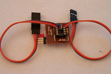
Suggested Construction Method
Here is a suggested method of constructing a servo switch
using standard components.
This layout with standard components weighs approximately
7gms when assembled,
and covered with heatshrink.
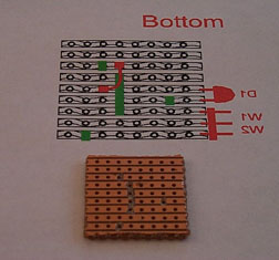
The servo switch is constructed on a small piece of veroboard, or
other similar prototyping board. The complete layout is as follows:
Important Note:This layout makes a few optimisations to
the circuit diagram for the switch. In particular:
- The position of D1 and R4 are reversed so that the LED is
connected to the PIC pin and the resistor goes to ground. This
minor change made the layout simpler.
- Jumpers W1 and W2 are constructed using only 3 header pins.
The switch only requires one jumper can be installed at any time.
The common ground pin for W1 and W2 is in the middle of the three pins.
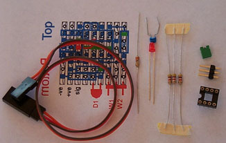
Step 1
Obtain all the parts you will need.
It is probably worth using a socket for the 12F675 as you may
want to reprogram the PIC - spend a few extra cents
and purchase a 'machined' socket with the round pins.
The jumper pins can normally be obtained in continuous strips,
you just break off what you need. The jumper to put on the
pins can be obtained from dead PCs, and many other sources.
A 30cm servo extender cut in half makes an ideal servo
input and output cable for the switch.
Step 2
Print off the bottom view of the veroboard layout and cut
a piece of board the same size. I normally
cut with a knife along the holes on both sides of the board and
then snap along the line I have just cut.
Remove the copper tracks in the positions indicated by the
green lines on the bottom view - like this:
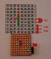
Step 3
Install the one wire jumper on the bottom of the board, this
should be insulated wire and you should check that you have not
made a short with the nearby tracks.
At the same time install the jumper pins and the LED.
Note that the LED must be installed the correct way round. The LED
normally has one leg longer than the other and also has a 'flat' spot
on the plastic housing next to the shorter leg. Install the LED
with the longer leg connected to pin 2 of the PIC.
Like this:
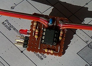
Step 4
Now turn the veroboard over and use the top view of the layout,
the top wiring is indicated by the blue lines.
Solder the components onto the board in the following order:
- The wire top (blue) links
- The resistors
- The IC socket
- The capacitor
- The servo connection wires. Take care to ensure that no
stray wires short out between the servo cables. If you tin
the wires first you may need to enlarge the holes in the
veroboard slightly.
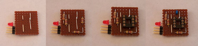
You should end up with something like this:
Step 5
Now you should have the entire switch assembled, so now we can
check it out. Proceed as follows:
- Check for shorts between the tracks on the veroboard, run
a knife along between the tracks to remove any solder shorts
etc.
- Plug the servo switch into your receiver, select a channel
with a left-centre-right, or up-centre-down control.
- Make sure that there is no PIC in the socket.
- Power on your transmitter and then the receiver system.
- Check the voltage
between pins 1 and 8 of the IC socket, you should see 5V. Also
check the voltage on the power pins of the servo output
connector and ensure that it is 5V.
- Using a small piece of wire, or similar jumper, short
together pins 1 and 2 of the socket. The LED should light
up. If it doesn't it could be that you have installed the LED
the wrong way round.
- Remove the power.
- Insert a correctly programmed PIC.
Double check that you have the PIC in
the correct way and that pin 1 of the PIC is in the correct place.
- Ensure that there are no jumpers installed on the switch.
- Connect a servo to the servo output lead of the switch.
- Turn on the receiver system.
- The output servo should move to its middle position, and the
LED should be off.
- Move the transmitter control for the channel you have the
switch plugged into to one extreme, back to centre, to the
other extreme and back to centre. At one of the extremes the
switch LED should light for about 0.5 seconds, at the same
time the servo should move to one extreme and then back to centre.
- Now wait for 55 seconds. After 55 seconds the LED should
flash and the servo move again - this is the switch keeping the
camera powered on by automatically taking a photograph.
- Now place a jumper on the Video Mode pins and wait
for another 55 seconds. This time the LED should flash twice
and the servo move twice to activate the shutter. Once to start
recording a video segment and the second time to stop recording.
- Turn off the receiver system.
- Remove the Video Mode jumper and place it on the
Programming Mode position.
- Apply power to the receiver system.
- The LED should be flashing rapidly to indicate that programming
mode is active.
- Remove the Programming Mode jumper.
- The LED should now flash a single 'short' flash.
- Move the input control to one extreme and back to centre.
- The LED will now be flashing either a single 'long' flash
(in which case the stick direction corresponds to 'decrement'
in programming mode),
or two 'short' flashes (in which case the stick direction
corresponds to 'increment').
- Remove the power.
Step 6
Congratulations - you now have a fully functional servo switch.
You use two small blobs of electrical silicon,
and a small amount of nail polish if desired,
to hold the
servo leads to the veroboard.
Then use a short length of heat shrink to cover the switch.
Step 7
You should now proceed with configuring the switch as described
elsewhere in this document so that it functions as you require.
Frequently asked questions
Q: Do I have to program all 11 parameters?
A: No. The servo switch comes configured with an initial set of
parameters. Many of these may be suitable as-is. However, at a minimum
you will need to program the output servo positions.
Q: Is there a recommended programming sequence?
A: Yes.
Q: Do I have to program the parameters in any particular order?
A: No. You can program the parameters in any order you like.
Q: I can't get the programming mode to work reliably?
The stick movement doesn't always increment/decrement the number.
A: Ensure that the trim is in the middle for the channel you are using
for programming and also that the ATV values are set to 100% during
programming. The switch must see servo control inputs less than
1.375msec at one end and greater than 1.625 at the other end.
Q: Do I need to use the MPLAB IDE to build this switch?
A: No. This switch is completely configurable by the end-user,
and a .HEX file is supplied that you can use to program the 12F675. You
do however need to be able to program a 12F675 from a .HEX file.
Microchip have a PICkit-1 available for US$36 that includes a USB
based 12F675 programmer, a 12F675 and all the software you will need.
Q: Exactly which Microchip part do I use?
A: The manufacture's part number you want is 'PIC12F675-I/P'
- this is the 8-pin DIP standard version (-40 to +85 degrees C).
You can also use the extended temperature range version 'PIC12F675-E/P',
although this will cost a bit more (-40 to +125 degrees C).