| Step |
|
Description |
| Before you start |
 |
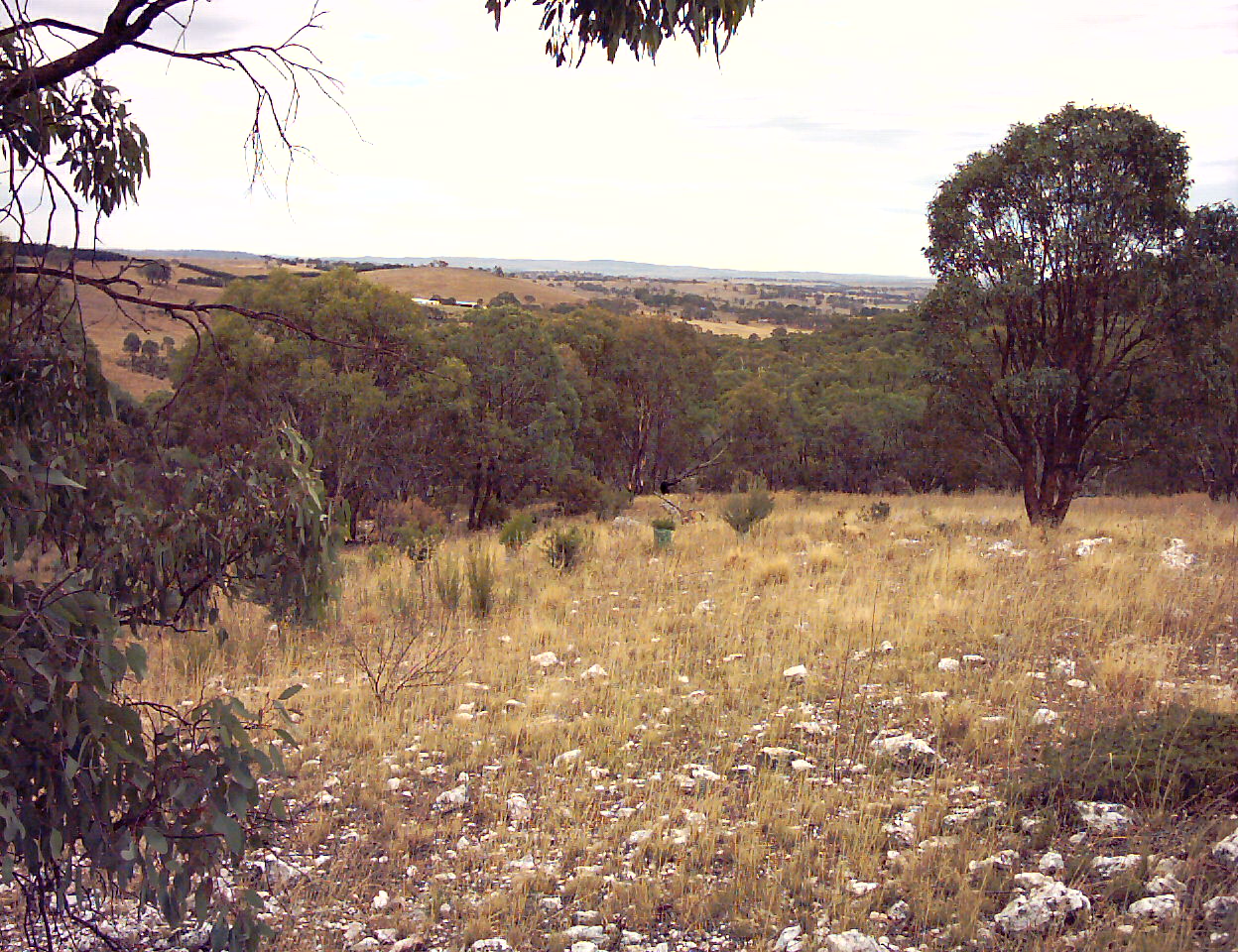
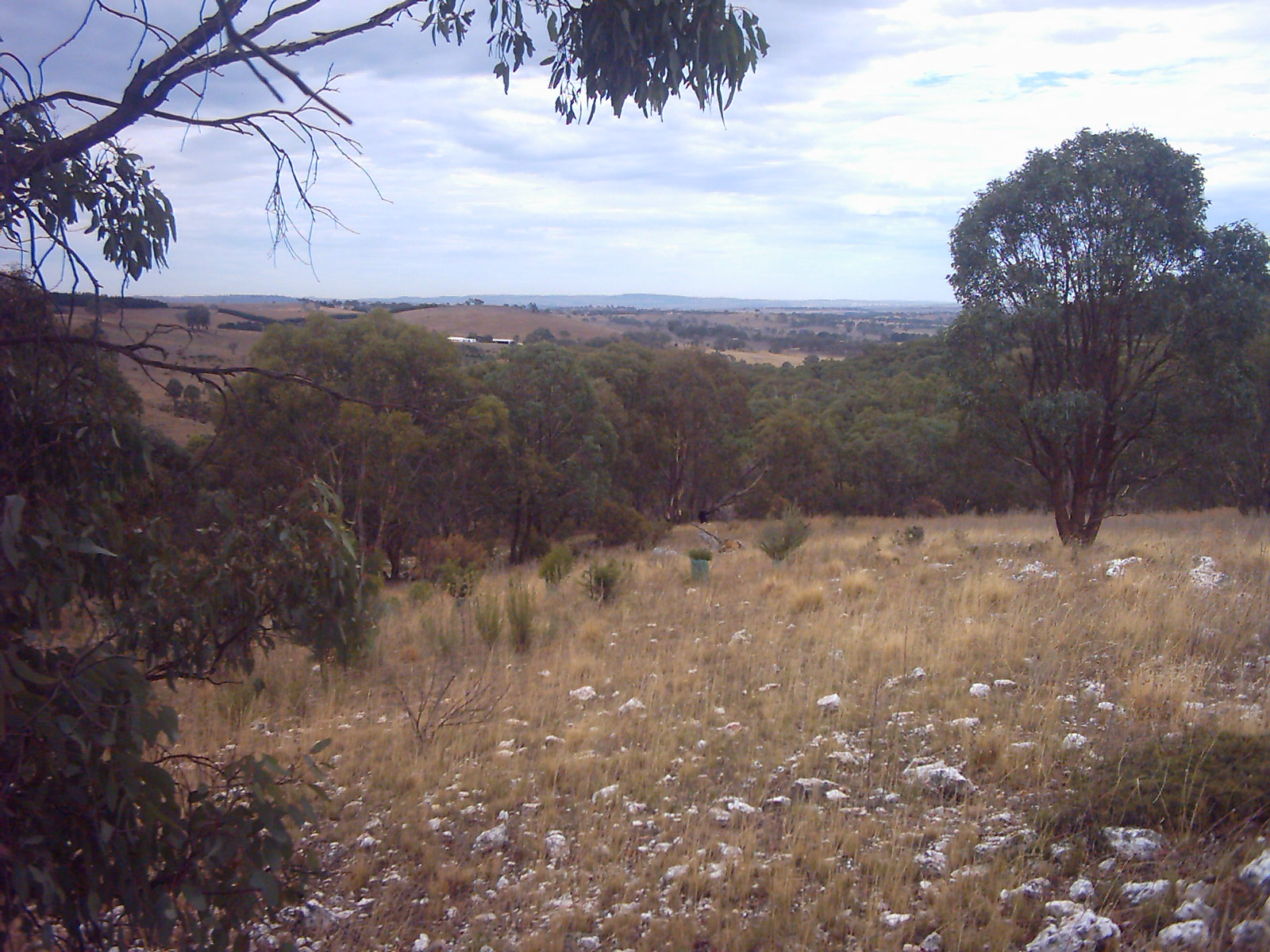
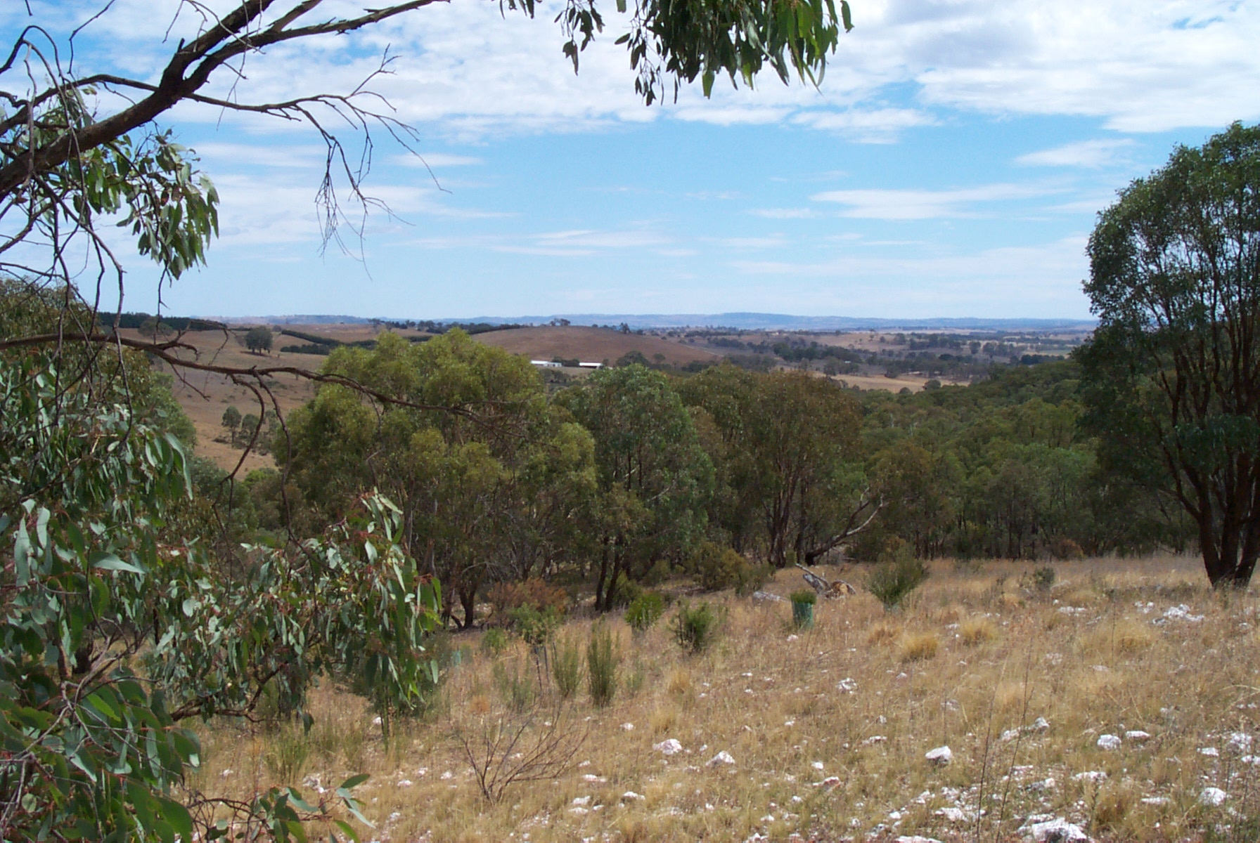
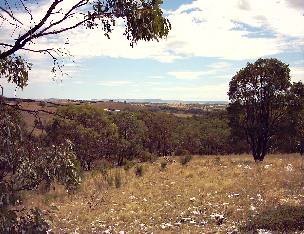
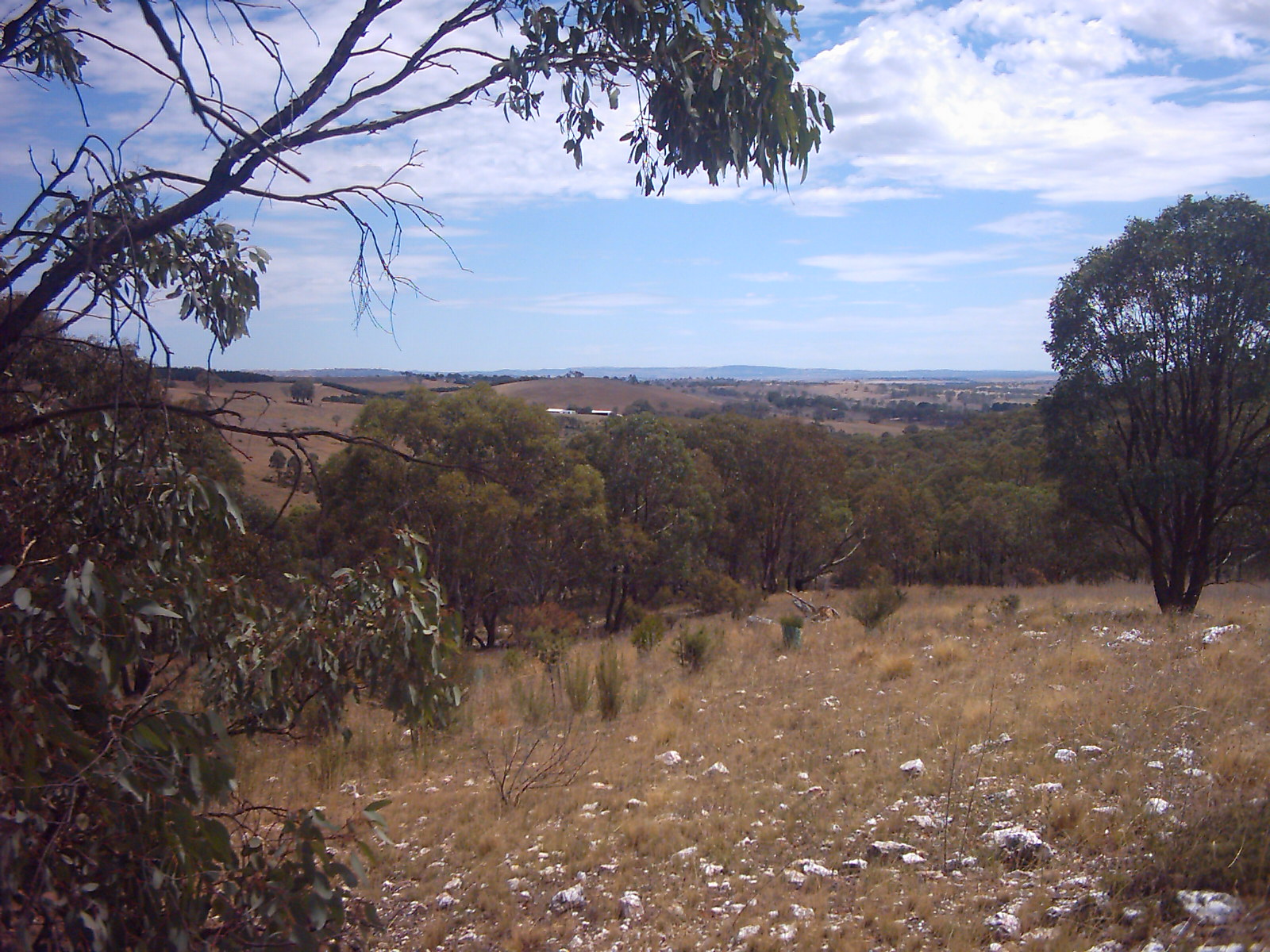
Before you open up your camera take a number of reference photos
and store them away. You will need these photos later to ensure that
you have not disturbed the focus of the camera.
Try and shoot photos in good lighting conditions, also ensure that
there are distant objects to check for focus.
Ideally you need to have objects in the various corners and sides
of the image, not just in the centre area.
|
| 1 |
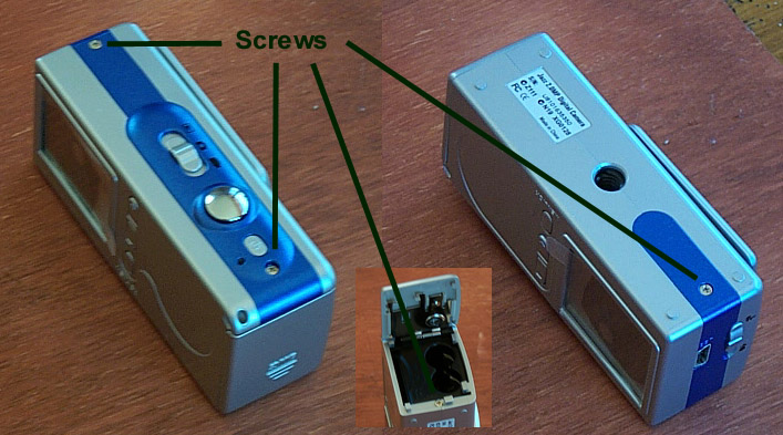 |
Locate the four small screws that hold the case together. There
are two on the top of the camera, one on the bottom, and one inside
the battery cover.
Remove these screws.
Note:If you are worried about scratching the LCD
panel then leave the protective plastic in place until
you have finished this procedure.
|
| 2 |
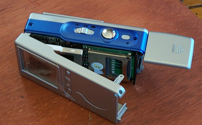 |
Cut the serial number label down the middle to allow the case
parts to separate. This voids your warranty.
Open the battery compartment door and
starting at the USB connector end and moving to the battery
cover gently remove the back cover.
Ensure that the LCD display separates from the plastic case.
It is connectecd to the main circuit board by a short flexable
circuit board.
Completely remove the back cover.
|
| 3 |
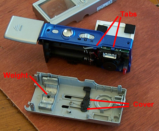 |
Ensure that the focus setting is in the 'mountain and people'
position - this is important later.
Hold the blue strip in your right hand and using your
left hand gently pull the front cover away from the camera.
There are some locking tabs on the top of the blue
strip that you need to ease the case over.
Completely remove the front cover.
|
| 4 |
 |
Unscrew the weight and discard this.
You have just saved yourself 6 gms.
|
| 5 |
 |
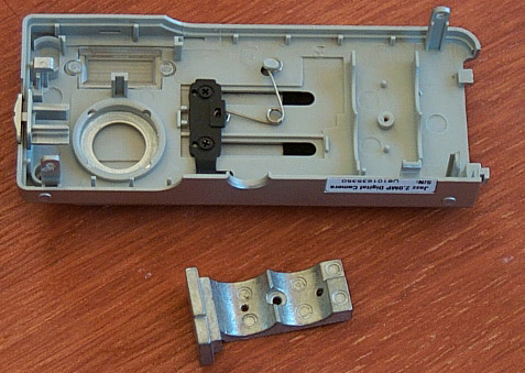
You may elect to remove the sliding lens cover.
This will save you another 3-4gms. However, it will
also leave you some holes in the front of the case.
You can cover the holes with tape to protect the inside of the camera.
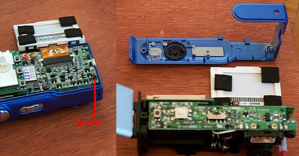
To do this unscrew the two screws holding the lens cover on.
Remove the black plastic, the spring, and the sliding cover
from the front of the case.
Solder the switch contacts together so that the camera sees
the cover as 'open'.
Even if you are not going to remove the sliding lens cover
you still may want to solder the switch contacts together. This
will stop the camera powering down mid-flight if the cover
moves.
|
| 6 |
 |
Remove the blue band.
First remove the small screw that is securing the band.
Start on the bottom of the camera and loosen the band,
it will come away easily.
Keep your fingers away from the flash unit area.
|
| 7 |
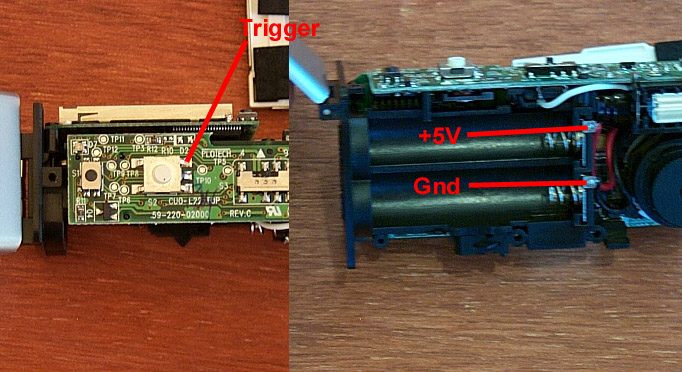 |
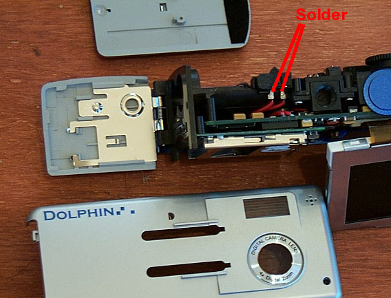
Attach the power supply and camera trigger signals to
the places indicated. Make sure that you cover the camera lens
while soldering to the battery terminals to ensure that you
do not get anything splattering into the lens.
Do not play with the focus ring on the camera. If it is
rotated clockwise past the 'mountains and people' setting the entire
lens will pop off - this exposes the CMOS sensor array.
The lens can be put back on by pushing down and rotating back to
the original position - however this may result in problems with the
focus.
|
| 8 |
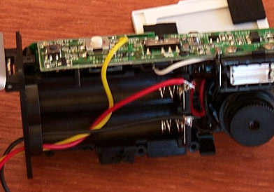 |
Feed the wires out through the battery case.
|
| Focus 1 |
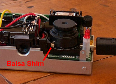 |
Now is your opportunity to adjust the focus.
My camera had an out of focus area down the right hand side
of the image. I corrected this by placing a balsa shim
under the side of the lens assembly.
The lens will move slight from side to side and up and down.
If you have a focus problem then take a series of images while
applying slight pressure to the side of the lens. This will
allow you to determine which way the lens needs to move to
correct the focus problem.
I placed the shim by rotating the lens so that it popped off
and then placing the balsa on top of the metal spring and replacing
the lens. Note: take great care not to damage, or get junk in,
the CMOS sensor.
To get the lens assembly off
take a small wooden implement, such as a sturdy toothpick or a bamboo
skewer and pry the plastic detent arm away from the lens barrel.
(Use wood as you may damage the electronics if a metal object is used
and you inadvertently let it slip). Then press down lightly on the
lens barrel and rotate it clockwise. It will hit a stop
at which point you can lift the assembly clear of the mount.
|
| Focus2 |
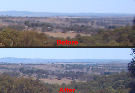 |
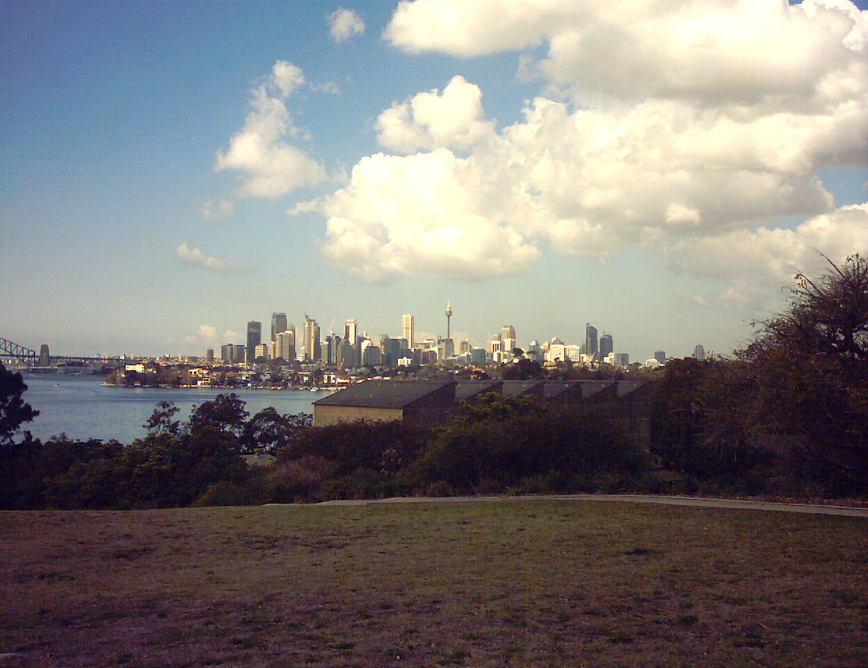
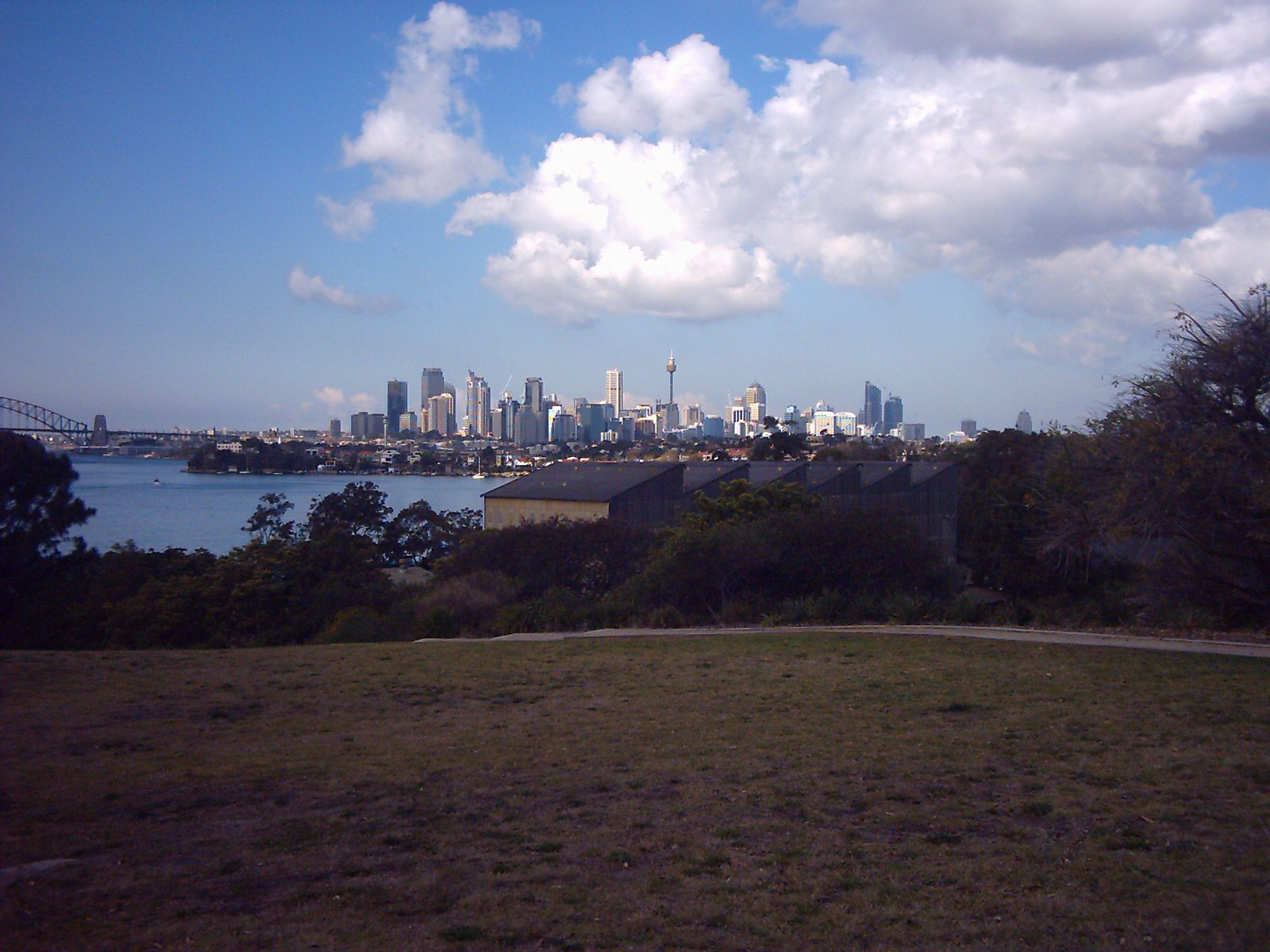
There is some trial and error in getting this correct. Eventually
I got the image focus to an acceptable point.
The image on the left shows a small section from the top
right hand corner of the image before and after the adjustment.
|
| 9 |
 |
Start to reassemble the camera, put the blue band
back on again. Take care to fit the switches back correctly.
Replace the small screw.
Then put the camera front on, make sure that the focus
control is in the 'mountains and people' position. Note:
if you have adjusted the focus (for example using balsa shims) you
may wish to remove the focus control from the camera. This
will stop it getting accidentally moved and destroying your adjusted
focus setting.
Clean the LCD display with a soft cloth and put the back
of the camera on.
Replace the four screws.
|
| 10 |
 |
File a slot in the end of the battery door to let the wires
out, then close the battery door.
|
| 11 |
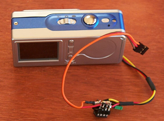 |
Connect your electronic switch to the wires.
|
| 12 |
 |
Now you should retest the focus and lens assembly by taking some
more photos and comparing them to your original shots.
You can take these photos using the switch to test that it is
all working correctly.
|
| 13 |
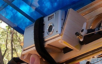 |
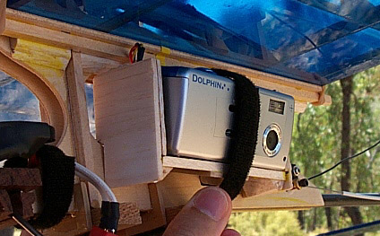
Mount the camera.
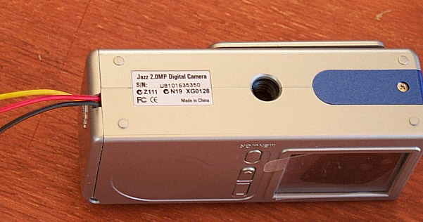
If you want to use the tripod screw thread as part of the mounting
system the required bolt is 1/4" x 20. You can use cutdown nylon
wing bolts from Great Planes (P/N GPMQ4402).
|


